You have chosen the wavelength, optical power, and package for your laser diode. Then you open a driver datasheet and find current limits, maximum compliance voltage, modulation inputs and several different operating modes. Which of those numbers actually matters for your system?
A laser diode driver supplies controlled electrical current to a laser diode. Its performance affects how steadily the laser operates, how it responds to control signals, and how it behaves during startup and shutdown. Depending on the design, it also provides protections against conditions that could damage the diode.
Choosing one starts with understanding the diode’s electrical requirements and the way you intend to use it. This guide explains the essentials, from basic current control to selecting a high-power laser driver, with practical examples along the way.
What Is a Laser Diode Driver?
A laser diode driver is an electronic circuit or instrument that regulates the current flowing through a laser diode. You may also see it called a laser driver, diode driver, or laser diode current source.
The laser diode produces the light. The driver controls the electrical conditions that allow it to do so predictably.
For example, if your application calls for a particular operating current, the driver attempts to maintain that current as conditions change, within its specified limits. A driver designed for modulation can also vary the current when you want the laser output to change.
Laser diode drivers range from small modules integrated into equipment to complete laboratory instruments with displays and computer interfaces. Their capabilities differ, so the word “driver” alone does not tell you how much current, protection or control a product provides.
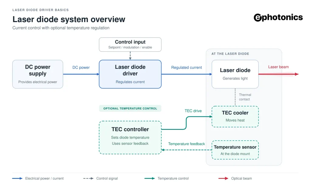
Figure 1. The laser diode driver controls electrical current, while an optional temperature controller regulates the diode’s temperature.
Why Does a Laser Diode Need a Dedicated Driver?
A laser diode’s electrical behavior makes precise current control important. A small change in applied voltage can cause a substantial change in current, and the operating point also changes with temperature.
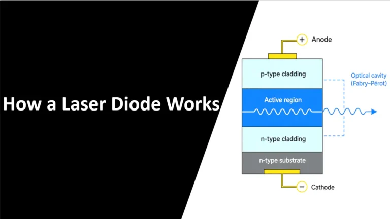
Above the lasing threshold, increasing current generally increases optical output over the diode’s normal operating range. Excessive current can overheat or damage the device. Our explanation of how a laser diode works covers the relationship between current injection, threshold, and laser emission.
A dedicated driver is designed around this sensitivity. Useful features include an adjustable current limit, controlled startup, and protection against specified electrical faults. These features vary between products; they should be checked rather than assumed.
A laboratory power supply may offer constant-current operation, but that alone does not establish suitability. Startup overshoot, stored energy at the output, and the response when the load changes also matter. A steady reading on the display cannot tell you everything that happens during a brief transient.
The practical question is whether the source can control the diode throughout the intended operating sequence, including the moments when you turn it on, change the setpoint, and turn it off.
How Does a Laser Diode Driver Work?
In a basic current-control loop, the driver compares the requested current with the current actually flowing through the diode. It then adjusts its output to reduce the difference.
The requested value is the setpoint. Depending on the product, you set it with a knob, an external voltage, software, or another interface. The driver measures current, commonly using a sensing resistor, and continually corrects the output while operating within its limits.
Two settings deserve separate attention: operating current and current limit. The operating current is what you ask the laser to use. The current limit defines the ceiling the driver is configured to enforce. Set both deliberately; the driver’s maximum capacity is not automatically an appropriate setting for the diode.
Constant Current vs. Constant Power
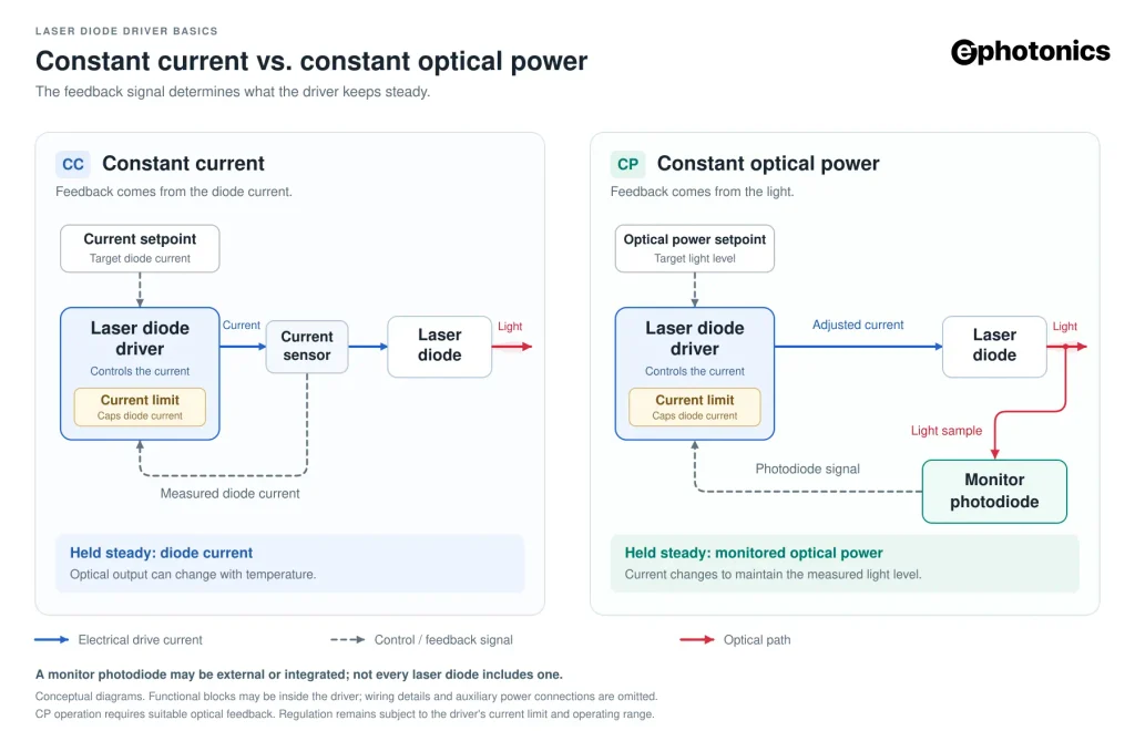
In a laser diode driver, CC holds current steady, while CP adjusts current to stabilize the monitored optical output.
| Compare | CC Constant current | CP Constant optical power |
|---|---|---|
| Regulated quantity | Diode current at the selected setpoint. | Monitored optical power at the selected setpoint. |
| Feedback signal | Current measurement in the driver’s control loop. | Signal from a compatible monitor photodiode. |
| Current behavior | Stays at the setpoint during steady operation. | Changes as needed to maintain the monitored light level. |
| Optical output | Can vary with diode temperature and operating conditions. | Held at the target within the feedback system’s range and the driver’s limits. |
| When to choose it | When direct control of diode current is the priority. | When stable monitored light output is the priority and optical feedback is available. |
| Current limit | Set an appropriate limit for the diode. | Set an appropriate limit; the target power may not be reached if more current would be required. |
Photodiode feedback: CP requires compatible, correctly scaled optical feedback. The monitor photodiode may be integrated or external; not every laser diode includes one. Temperature control remains a separate function. Check the driver’s supported modes and feedback requirements.
Linear and Switching Laser Drivers
Drivers can regulate power in different ways. A linear output stage controls current while dissipating the voltage difference across the regulating electronics as heat. For example, a simplified linear stage dropping 5 V at 2 A dissipates about 10 W, before other losses are included. That heat must go somewhere.
A switching driver transfers energy through rapidly switched circuitry. This can improve efficiency, especially as electrical power increases, although switching ripple and interference need to be controlled. Hybrid designs combine switching conversion with a linear regulating stage. Manufacturer designs illustrate both approaches, including switching power conversion and combined switching and linear regulation.
The topology is a starting point for comparison. Your application still needs measured noise performance, adequate cooling, and suitable response speed. A label such as “linear” or “switching” cannot answer those questions by itself.
Packaging is a separate decision. A laboratory instrument offers convenient controls for experimentation; an OEM module can be easier to integrate into a machine. Include the external supply, cooling, and control hardware when comparing the space each solution needs.
CW, Pulsed, and QCW Operation
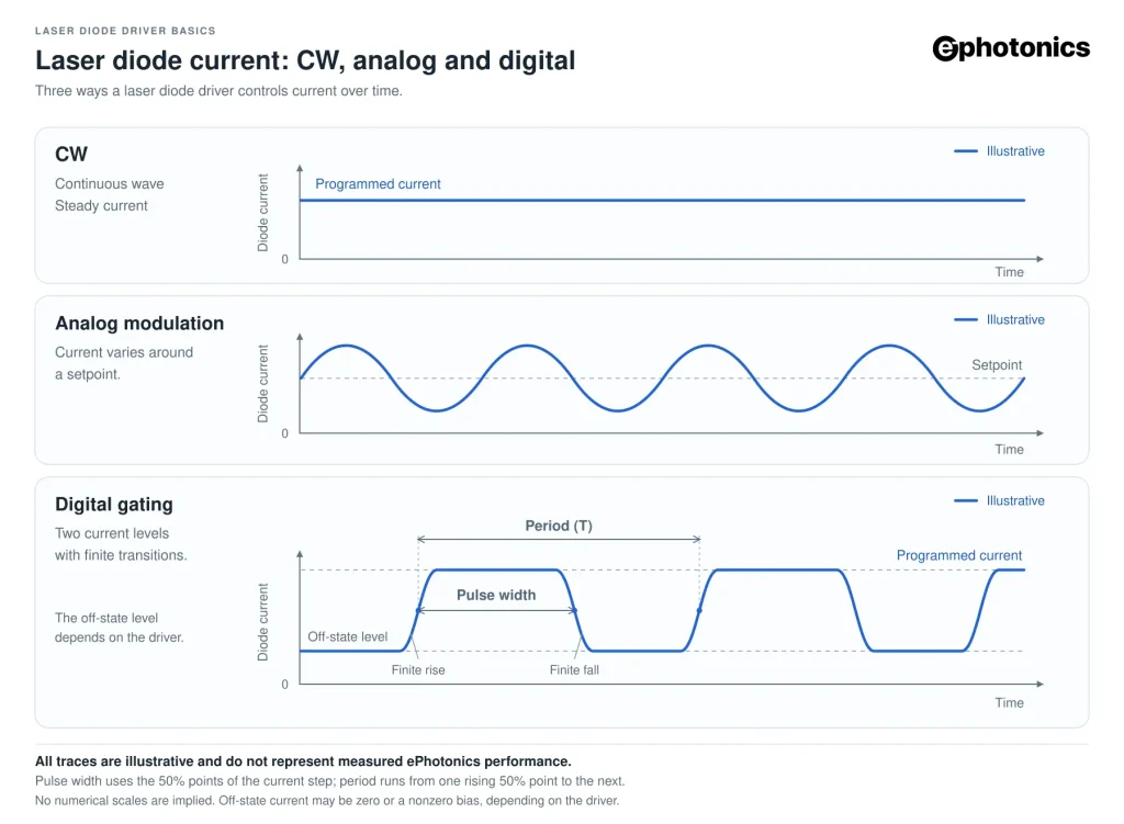
In continuous-wave operation, or CW, the laser emits continuously. The diode, driver, and cooling system must support the sustained operating point.
A pulsed laser diode driver delivers current in bursts. To describe those bursts, you need more than a frequency: pulse width tells you how long each pulse lasts, repetition rate tells you how often it occurs, and duty cycle tells you the fraction of time spent on.
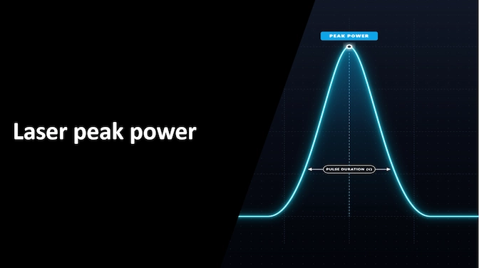
For example, one 100-microsecond pulse every millisecond gives a 10% duty cycle. If the optical pulses were flat at 20 W, with negligible light between them, average optical power would be approximately 2 W. That is an illustrative calculation, not a performance claim for a particular laser.
Quasi-continuous-wave, or QCW, commonly describes pulses long enough for approximately steady laser operation during each pulse, with pauses that reduce average thermal loading. It is one type of pulsed operation; the label does not specify all timing limits.
Short pulses and high repetition rates place different demands on the electronics. Published drivers specify pulse width, rise time, repetition rate, and peak current separately, as illustrated by pulsed driver specifications.
Check those limits together with the diode’s ratings. A reduced duty cycle does not automatically permit more current than the diode allows under the specified pulse conditions.
Analog Modulation and Digital Gating
Modulation lets you change laser output during operation. Two common methods are analog control and digital gating.
An analog input changes the requested current or power according to an input signal. For instance, a driver might map an input-voltage range to an output-current range. The conversion, permitted voltage, and any internal offset are specific to the product. Some inputs add to an existing setpoint; others replace it. Before connecting a signal generator, check the input range and transfer function so the control signal stays within the driver’s specified limits.
Digital gating switches between defined output states, often using a logic signal such as TTL. The on-state current is usually set separately. Changing pulse width can change average output without changing the programmed on-state current.
An enable input may behave differently from a pulse input. It can start a delay, a startup ramp, or a fault-checking sequence. Some manufacturers explicitly separate these functions in their enable and pulsing instructions.
Also distinguish repetition rate from pulse shape. A driver may respond at the requested frequency while producing rounded edges or a pulse too short to reach its full current. Check rise time, fall time, pulse width, and modulation depth under relevant load conditions.
High-Power Laser Diode Drivers: What to Look For
A high-power laser driver must satisfy current, voltage, and thermal requirements at the same time. Looking only at the largest wattage printed on the page can hide an unsuitable match.
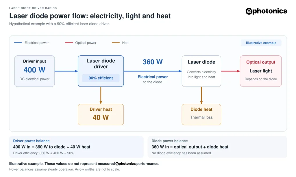
Separate electrical power from optical power
That 360 W figure describes electrical power delivered to the module. Optical output depends on the diode’s efficiency and operating conditions; part of the electrical input becomes heat in the laser assembly.
| Power at the driver | 90% efficiency | 95% efficiency |
|---|---|---|
| Electrical input to driver | 400 W | ≈ 379 W |
| Electrical output to diode | 360 W | 360 W |
| Heat dissipated inside driver | 40 W | ≈ 19 W |
Driver losses only: These hypothetical values are rounded. The diode has its own cooling requirement in addition to the heat produced by the driver.
Match both current and voltage
Emitters connected in series require the sum of their forward voltages. Check the electrical configuration when selecting a driver for fiber-coupled laser diodes or other multi-emitter sources.
Example: an 8 A, 45 V load
Driver rating: 10 A, 30 V
The current rating is sufficient, but the voltage rating is too low. This driver cannot meet the required operating point.
Check lower-voltage loads too
A high-voltage driver may have operating restrictions that make it unsuitable for a much lower-voltage load. Confirm the supported load-voltage range and operating conditions.
Include cooling and wiring in the selection
Check the conditions behind the published ratings. A high-power laser driver’s usable performance depends on its cooling arrangement and electrical connections.
| Selection factor | What to check |
|---|---|
| Cooling conditions | Confirm the required baseplate temperature, airflow and ambient temperature for the published ratings. |
| Duty cycle | Check that the ratings apply to your intended continuous or pulsed operation. Duty cycle affects heating and usable performance. |
| Cables and connectors | They must carry the full operating current. Their resistance causes voltage drop and heating, so check their ratings alongside the driver. |
| Pulse wiring | Plan cable length and routing with the electronics. Connection inductance can affect fast pulses. |
The Specifications That Matter When Choosing a Driver
Start with the specifications that affect your actual operating point, then consider convenience features. The application helps set your priorities: a continuously operated pump diode needs sustained electrical and thermal performance, while a source synchronized with a camera also needs suitable timing. For a sensitive optical measurement, small current fluctuations may deserve much closer attention.
The following questions make a useful comparison checklist.
Can it regulate the required current accurately?
Check the usable current range, accuracy, and adjustment resolution. Resolution describes the smallest setting change; accuracy describes how closely actual current follows the requested value. Neither is the same as maximum current capacity. A driver sized for tens of amperes may be an awkward choice for a diode needing very small current adjustments. Choose a range that fits the work you need to do.
Does it have enough compliance voltage?
Compliance voltage is the maximum output voltage available while the driver maintains current regulation under the stated conditions. It must cover the diode’s forward voltage and relevant connection losses. If the load needs more voltage than the driver can supply, the requested current cannot be maintained.
Are noise and stability specified meaningfully?
Noise describes relatively rapid current fluctuations, while long-term stability describes slower changes in output current over time. A laser diode driver may perform well in one area without necessarily performing equally well in the other.
Compare noise specifications over the same measurement bandwidth and under similar operating conditions. A noise value without its bandwidth, load, current setpoint and measurement method can be misleading. The reference source, current-sensing circuit, control loop, power supply, grounding and external connections can all influence the measured noise.
Does it protect against the faults relevant to your setup?
Look for documented current limiting, startup behavior, and fault responses. Other useful functions may include overtemperature shutdown, reverse-voltage protection, and interlock connections. Check exactly what each protection covers: protection at the supply input is different from protection at the laser output.
An interlock input can support a system shutdown function. The complete laser system still needs appropriate enclosure, beam control, and safety measures for its application.
When Do You Need Temperature Control?
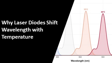
Current control and temperature control address different variables. Even with stable current, changes in diode temperature can change optical output and wavelength. That can matter when the laser must stay near an absorption line or pump another laser efficiently.
A thermoelectric cooler, or TEC, transfers heat between its two sides. A temperature controller reads a temperature sensor, typically a thermistor, and adjusts the TEC current to keep the laser diode near the selected temperature. The overall thermal design still matters: the heat sink must dissipate both the heat removed from the laser assembly and the additional heat generated while powering the TEC.
A laser diode driver with TEC control combines current and temperature functions in one unit. Check the laser channel and TEC channel separately, including their current, voltage, and sensor requirements.
Not every laser needs a TEC. Some applications use passive heat sinks, fans, or liquid cooling. The goal is to maintain suitable operating conditions for the diode and the application. Our guide to laser diode wavelength and temperature tuning explains the connection in more detail.
Practical Integration Checks Before Connecting a Laser Diode
Matching the headline current and voltage ratings is only the first step. This is where many otherwise sensible designs run into trouble. Before connecting an expensive diode, make sure the driver, power supply, wiring, grounding and cooling work as one system. The checks below catch problems that a maximum-current specification cannot reveal on its own.
Confirm the output topology and grounding
Laser diode packages may be cathode-grounded, anode-grounded or electrically isolated. Some connect one electrode to the metal case, which may also touch a grounded mount or heat sink. Check that the driver supports the diode’s polarity and grounding arrangement before attaching an oscilloscope, signal generator or computer. An unexpected ground path can bypass current sensing or short part of the output stage.
Calculate compliance voltage at the actual operating point
The driver must provide enough load voltage for the diode and the complete current path. A useful first estimate is:
Required load voltage = maximum diode forward voltage + operating current × total cable-and-connector resistance
Use the diode’s forward voltage at the intended current and temperature, not just a typical room-temperature value. Then add the margin and supply requirements specified by the driver manufacturer. Our laser diode driver compliance-voltage calculator can estimate cable drop and wiring loss.
Check safe operating area and thermal derating
A current and voltage combination can sit below both headline maximums and still exceed the driver’s thermal limit. In a linear output stage, the voltage dropped inside the driver multiplied by current becomes heat. Switching designs reduce this loss, but they still need cooling. Check the published safe operating area, baseplate or heat-sink requirement, ambient-temperature limits and any duty-cycle derating. Remember that the driver and laser diode are separate heat sources.
Plan wiring and remote sensing
At high current, even a small resistance matters. Keep the laser-current loop short, use conductors and connectors rated for the full current, and route fast pulse connections according to the manufacturer’s guidance. If the driver provides remote-sense terminals, connect them exactly as documented so regulation happens at the intended measurement point. Remote sensing can compensate for steady wiring drop, but it cannot remove cable heating or the effects of excessive inductance.
Use a controlled first-power-up procedure
- Review the diode and driver manuals, including polarity, grounding, interlock, cooling and connection order.
- With power removed, verify the wiring and configure the current limit below the diode’s applicable maximum rating.
- Where the manufacturer permits it, test the driver first with an approved dummy load rated for the required current, voltage and power.
- Check startup, shutdown and modulation behaviour with measurement equipment and probing methods suitable for the circuit.
- Connect the laser diode only after the dummy-load test is satisfactory. Begin at a conservative setpoint and increase current gradually while monitoring current, temperature and optical output.
Important: follow the diode and driver manufacturers’ instructions whenever they differ from this general sequence. Laser diodes are ESD-sensitive, and high-power laser systems require suitable electrical and laser-safety controls.
Worked example: an 8 A, 45 V diode module
Assume a module may require 45 V at 8 A and the complete outgoing-and-return wiring path has 0.07 Ω of resistance. The wiring drop is 8 A × 0.07 Ω = 0.56 V, so the load path may require at least 45.56 V before applying any manufacturer-specified margin. A 10 A, 30 V driver has enough current but cannot reach the voltage. A suitable higher-voltage driver must still be checked for its supported load range, input-supply requirement, cooling and modulation limits.
Common integration problems
| Symptom | Possible cause | What to verify |
|---|---|---|
| Current will not reach the setpoint | Insufficient compliance voltage or excessive wiring drop | Diode forward voltage, cable resistance, connectors, input supply and driver status |
| Driver overheats at steady current | Excess internal dissipation or inadequate cooling | Safe operating area, supply voltage, baseplate temperature, airflow and mounting |
| Optical output is noisy | Current noise, grounding, supply ripple, feedback instability or EMI | Measurement bandwidth, cable routing, grounding, shielding, load and supply conditions |
| Pulses are rounded or too small | Driver bandwidth, cable inductance or pulse width is insufficient | Rise/fall time, minimum pulse width, load conditions, connection length and probe setup |
| Fault occurs when test equipment is attached | Incompatible grounding or an unintended ground path | Driver output topology, diode case connection and instrument earth references |
How to Match a Laser Diode Driver to Your Diode
Begin with the datasheet for the actual diode or module. Its wavelength and optical-power label do not provide enough information to choose the electronics.
Write down the intended laser diode drive current, forward-voltage range, temperature conditions, and electrical pin configuration. Then add the operating mode, pulse requirements, control interface, and protection needs. This gives you a short list of requirements you can compare against driver specifications.
Pay attention to connections as well as numbers. Some diode packages connect an electrode to the metal case. Confirm that the driver’s output arrangement is compatible with the diode, its mount, and the rest of the system before connecting test equipment.
Laser Diode Driver FAQs
What does a laser diode driver do?
A laser diode driver supplies controlled electrical current to a laser diode. It helps keep the operating point stable and may provide current limiting, soft start, modulation and fault protection. The available functions depend on the model. The driver must be matched to the diode’s current, voltage and operating requirements.
Can I connect a laser diode directly to a power supply?
A standard voltage supply should not be connected directly to a bare laser diode without suitable current regulation and protection. Small voltage changes can cause large current changes. A bench supply’s current-limit setting alone does not establish low noise, controlled startup or protection against fast transients.
How do I choose the right laser diode driver?
Start with the diode’s operating current and forward voltage, then check modulation, current noise, protection features, supply requirements and cooling. Confirm that the driver can deliver the required current and voltage together under your operating conditions. Use these requirements to compare laser diode drivers.
What is the difference between constant current and constant power?
Constant current (CC) regulates the current flowing through the diode. Constant power (CP) adjusts current using photodiode feedback to hold the monitored optical output steady. CP requires compatible feedback and an appropriate current limit. The monitor photodiode may be external or integrated; not every laser diode includes one.
Can I use an LED driver for a laser diode?
An LED driver is not automatically compatible with a laser diode. Matching current and voltage is only the starting point: ripple, startup behavior, overshoot and fault protection must also meet the laser diode’s requirements. Use an LED driver only when its performance has been verified for the intended laser application.
What makes a high-power laser diode driver different?
A high-power laser diode driver must deliver the required electrical power while managing losses and heat. Current, voltage, supply capacity, cooling, cables and connectors all matter. A wattage rating alone is insufficient: an 8 A, 45 V load requires 360 W of electrical output and a driver that can support that operating point.
Does a higher driver current rating mean more laser power?
No. The maximum current rating describes the driver’s capacity, not the current you should apply. The setpoint and the diode’s limits determine operation. A higher-rated driver can sometimes run a lower-current diode, but its minimum setpoint, adjustment resolution and noise must still be suitable at that current.
Is a linear or switching laser diode driver better?
Neither is universally better. Linear drivers can be attractive for low-noise operation, while switching drivers can offer higher efficiency. Actual performance depends on the design, supply voltage and load. Compare current noise, heat dissipation, operating range and modulation performance using equivalent measurement conditions.
Can a laser diode driver produce pulses or support modulation?
Only if it supports the required operating mode. Check pulse width, repetition rate, rise and fall times, peak current, off-state level and duty cycle. An enable input is not automatically a fast pulse input. Our laser pulse calculator and modulation simulator can help you explore pulse timing and duty cycle.
Does a laser diode driver also control temperature?
Not necessarily. Current regulation and temperature regulation are separate functions. Temperature control needs a sensor, suitable thermal hardware and a controller, which may be integrated or separate. A laser diode driver with TEC control combines these functions, but the cooling capacity must still match the thermal load.
Why are low noise and transient protection important?
Current noise can affect optical power stability or laser frequency. Fast transients can produce brief current excursions that a steady reading misses. Compare noise specifications over the same bandwidth and assess transient behavior separately. For an academic example, see research on stable, low-noise laser current drivers by Erickson and colleagues.
Does a driver’s wattage equal the laser’s optical output?
No. Electrical output is current multiplied by voltage: 8 A at 45 V is 360 W of electrical power. The optical output depends on the diode’s efficiency and operating conditions. Driver input power also covers losses inside the driver, so the driver and the diode have separate cooling requirements.