Fresnel Reflection Calculator
Reflectance · Transmittance · Refractive Index
| Polarization | Reflectance (R) | Transmittance (T) |
|---|---|---|
| S-Pol (Perpendicular) | ---% | ---% |
| P-Pol (Parallel) | ---% | ---% |
| Average (Unpolarized) | ---% | ---% |
ephotonics
linkedin.com/company/ephotonics
Follow our page for weekly laser engineering guides, photonics tutorials, and new calculator releases directly in your feed.
Follow on LinkedInHow the Fresnel Reflection Calculator Works
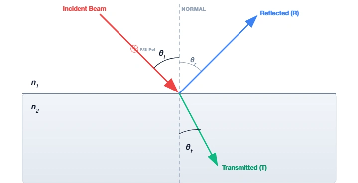
The Fresnel reflection calculator determines how much light is reflected or transmitted when it encounters an interface between two different materials (such as air and glass). This physical behavior is described by Fresnel's Equations.

The Fresnel Equations
Understanding the Variables:
Why calculate Fresnel Reflection?
- Power Loss: Up to 4% is lost at every single glass/air surface.
- Ghost Images: Reflections cause flare and artifacts in imaging systems.
- Safety: High-power back-reflections can damage laser sources.
- AR Coatings: Calculation is essential for designing Anti-Reflective layers.
The "Optical Tax" at Interfaces
Whenever light travels from one medium to another (e.g., from air into a glass lens), a portion of that light bounces back. This phenomenon is known as Fresnel Reflection. While it is the reason we can see our reflection in a window, in optical engineering, it is often a significant problem.
For standard glass (n ≈ 1.5) in air, the reflection loss is about 4% per surface at normal incidence. In a complex microscope or camera lens with 10 elements (20 surfaces), this could theoretically result in a loss of over 50% of the light if left untreated. Understanding and calculating these values allows engineers to maximize transmission efficiency.
Critical Engineering Applications
1. Anti-Reflective (AR) Coatings
The primary use of the Fresnel equations is in the design of thin-film coatings. By calculating the exact reflection based on refractive index, engineers can apply a dielectric layer with a precise thickness to create destructive interference.
2. Fiber Optic Coupling
In telecom, the small gap between two fiber connectors acts as a Fresnel interface. This creates "Fresnel Loss" (typically -0.17 dB) and dangerous back-reflections (Return Loss). Engineers use Index Matching Gel to eliminate the index difference (Δn ≈ 0).
3. High-Power Laser Safety
In multi-kilowatt laser cutting systems, a 4% back-reflection represents hundreds of watts traveling backward. This "back-reflection" can burn out the laser diode. Accurate calculation helps engineers design optical isolators to manage this energy.
4. Brewster Windows
By using this calculator, you will notice that at a specific angle (approx 56° for glass), the reflection for P-polarized light drops to exactly zero. This is Brewster's Angle, used in gas lasers for 100% transmission efficiency.
When light travels from a high-index medium (like glass) to a low-index medium (like air), there is a critical angle where refraction stops completely. Beyond this angle, 100% of the light is reflected back inside. This principle of Total Internal Reflection is exactly what traps light inside optical fibers.