Zener Diode Calculator
Series resistor · current · power · toleranceSupply and Zener diode
Use worst-case input limits and the data-sheet voltage tolerance.
Load and design current
The resistor must feed both the load and the Zener diode.
Planning calculator only. Verify component tolerances, temperature effects, safe operating area, and power derating against manufacturer data.
How the Zener Diode Calculator Works
A Zener diode can form a simple shunt regulator or voltage clamp when it is reverse biased and supplied through a series resistor. This Zener diode calculator selects an E24 resistor, checks the minimum and maximum Zener current, and estimates worst-case power in both the diode and resistor.
The design is evaluated at two corners. Minimum input voltage, maximum Zener voltage, and maximum load current determine whether regulation is maintained. Maximum input voltage, minimum Zener voltage, and minimum load current determine the highest Zener and resistor dissipation.
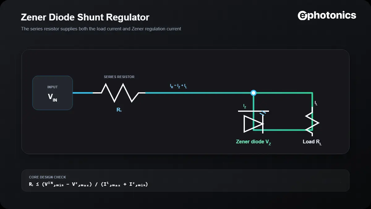
The chosen resistor must be no larger than this value if the required minimum Zener current is to remain available.
The current through the series resistor splits between the Zener diode and the load.
Both devices require margin and temperature derating; nominal room-temperature ratings are not enough for every enclosure or ambient condition.
How to Use This Zener Diode Calculator
- Enter minimum and maximum source voltage.
- Enter nominal Zener voltage and its data-sheet tolerance.
- Enter the minimum and maximum load current.
- Specify the minimum Zener current needed to remain in the intended regulation region.
- Enter the diode power rating and review current, power, and component-margin results.
Why use a lower E24 value? The exact result is a maximum resistance. Selecting the nearest lower standard value preserves current at the low-input corner, but it increases dissipation at high input—so both corners must be checked.
Worked Zener Diode Design Example
5.1 V shunt regulator
Use 12–14 V input, 5–15 mA load, 5 mA minimum Zener current, and a 5.1 V diode with ±5% tolerance.
- Maximum possible Zener voltage:
5.355 V - Maximum resistance:
(12 − 5.355)/(15 mA + 5 mA) = 332.25 Ω - Nearest lower E24 resistor:
330 Ω - At minimum input and maximum load, Zener current is approximately
5.14 mA - At maximum input and minimum load, current and power increase and must be checked against rated limits.
Zener Voltage Is Not Perfectly Constant
A real Zener diode is characterized at a specified test current. Its voltage changes with current because of dynamic impedance, and it changes with junction temperature according to its temperature coefficient. Tolerance, knee current, leakage, pulse duration, package thermal resistance, and PCB copper area all influence the result.
| Data-sheet item | Why it matters | Design use |
|---|---|---|
| VZ at IZT | Reference voltage at a stated current | Check your operating current is comparable |
| Voltage tolerance | Initial part-to-part spread | Evaluate VZ,min and VZ,max |
| Dynamic impedance | Voltage change with Zener current | Estimate load and line regulation |
| Knee current | Lower edge of useful breakdown region | Set a realistic IZ,min |
| Power derating | Allowable power falls with temperature | Check actual ambient and board conditions |
Common Zener Diode Design Mistakes
- Calculating with nominal input voltage only.
- Ignoring the load current that shares the resistor current.
- Using nominal Zener voltage without tolerance.
- Assuming any reverse current produces the rated Zener voltage.
- Checking diode power but not resistor power.
- Ignoring temperature coefficient and package derating.
- Using a small-signal Zener for surge energy without pulse-rating verification.
Safety note: this calculator is for low-voltage component design. It does not establish isolation, touch safety, surge compliance, or safe operation from mains-connected supplies.
Frequently Asked Questions
What does a Zener diode do?
A Zener diode is designed to operate in reverse breakdown, where it can hold an approximately constant voltage over a specified current range.
Why is a series resistor required?
The resistor limits current and drops the difference between input voltage and Zener voltage. Connecting an ideal voltage source directly across a Zener diode can cause destructive current.
How do I choose the minimum Zener current?
Use the data sheet’s test conditions, knee-current information, dynamic impedance, and the regulation accuracy required by the application.
How much power margin should I use?
Apply manufacturer derating for ambient temperature, PCB layout, package, pulse conditions, and reliability target. The calculator’s two-times resistor suggestion is only a starting point.
Can a Zener diode replace a precision voltage reference?
Sometimes for noncritical biasing or protection, but a dedicated reference generally provides better accuracy, drift, and low-current behavior.