
Shockley Diode Calculator
Current · voltage · temperature · dynamic resistanceOperating point
Enter the known electrical quantity. The other quantity is calculated instantly.
Diode model
Use data-sheet or fitted values for the saturation current and ideality factor.
Educational semiconductor model only. Validate device parameters and operating limits against the manufacturer data sheet and a full circuit simulation.
How the Shockley Diode Calculator Works
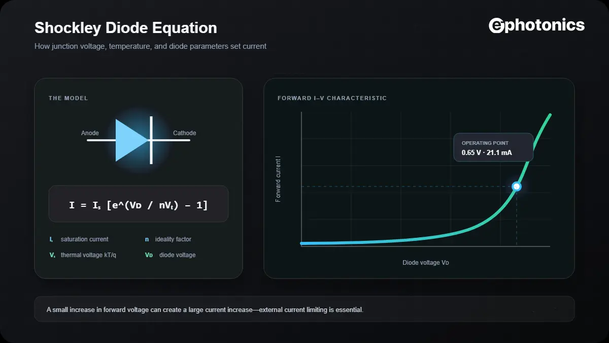
The Shockley diode equation describes the exponential relationship between the voltage across an ideal p–n junction and the current through it. This calculator solves the equation in either direction, adjusts thermal voltage for junction temperature, and reports the local dynamic resistance and diode power at the selected operating point.
Unlike a constant-voltage diode approximation, the Shockley model shows why a small increase in forward voltage can produce a large increase in current. It is useful for education, first-pass analysis, curve fitting, and checking a compact diode model before moving to a complete SPICE simulation.
The forward-positive diode current is determined by saturation current, diode voltage, ideality factor, and temperature-dependent thermal voltage.
The inverse form calculates diode voltage from current. In the ideal model, the entered current must be greater than −IS.
At 25°C, thermal voltage is approximately 25.69 mV. Temperature must be expressed in kelvin in the equation.
How to Use the Shockley Diode Calculator
- Choose Current from voltage or Voltage from current.
- Enter the known operating value and select its unit.
- Enter saturation current and ideality factor from a data sheet, fitted model, or laboratory measurement.
- Enter junction temperature—not merely the surrounding ambient temperature.
- Review the operating point, thermal voltage, dynamic resistance, power, and plotted I–V curve.
The example buttons demonstrate different mathematical behaviors; they are not substitutes for a manufacturer-supplied model. Saturation current can vary greatly between devices and changes strongly with temperature.
Dynamic Resistance and Diode Power
The slope of the I–V curve matters in small-signal and feedback analysis. Differentiating the Shockley equation gives the exact local incremental resistance:
When forward current is much larger than saturation current, this reduces to the familiar approximation rd ≈ nVT/I.
The calculator also reports P = VDI. This is the electrical power at the chosen operating point, but it does not predict junction temperature. A thermal model, package thermal resistance, and operating waveform are needed for that assessment.
Worked Shockley Equation Example
Room-temperature silicon-junction example
Assume VD = 0.65 V, IS = 1 nA, n = 1.5, and T = 25°C.
- Convert temperature:
T = 298.15 K - Thermal voltage:
VT = kT/q ≈ 25.693 mV - Normalized voltage:
VD/(nVT) ≈ 16.87 - Diode current:
I ≈ 21.1 mA - Dynamic resistance:
rd ≈ 1.83 Ω
When the Shockley Model Is Accurate—and When It Is Not
| Operating region | What the model captures | Main limitation |
|---|---|---|
| Moderate forward bias | Exponential p–n junction behavior | Accuracy depends on fitted IS and n |
| Very low current | First-order leakage and recombination trend | Surface leakage and multiple mechanisms may dominate |
| High forward current | Ideal junction exponential | Series resistance and self-heating flatten the real curve |
| Reverse bias before breakdown | Current approaches −IS | Real leakage can differ substantially |
| Avalanche or Zener breakdown | Not modeled | Use breakdown data or a Zener/SPICE model |
Engineering caution: never use this ideal equation by itself to set a safe current for an LED, laser diode, power diode, or Zener diode. Include the external circuit, series resistance, thermal behavior, tolerances, and absolute maximum ratings.
Common Calculation Mistakes
- Using ambient temperature: the equation requires junction temperature.
- Mixing current units: a value in nA differs from a value in µA by a factor of one thousand.
- Assuming n is always 1: practical fitted values depend on the device and operating region.
- Ignoring series resistance: the ideal equation can predict unrealistically large current at high forward voltage.
- Modeling breakdown: the basic Shockley equation does not describe Zener or avalanche conduction.
- Treating IS as constant over temperature: this parameter itself changes strongly with temperature.
Frequently Asked Questions
What is the Shockley diode equation?
It is an idealized exponential model relating p–n junction current to diode voltage, saturation current, ideality factor, and thermal voltage.
What is the ideality factor of a diode?
The ideality factor n is a fitted model parameter that represents how the measured junction behavior differs from an ideal diffusion-dominated diode. It is not universally identical for all diodes or operating currents.
Why does diode current rise so quickly with voltage?
Voltage appears in the exponent VD/(nVT). Once forward bias becomes several multiples of nVT, even a small voltage increase produces a large current increase.
Does the calculator model reverse breakdown?
No. The ideal equation approaches −IS under reverse bias. Avalanche and Zener breakdown require additional device parameters.
Can this calculator replace SPICE?
No. It is valuable for learning and first-pass checks, while SPICE models can include series resistance, capacitance, breakdown, temperature dependencies, and device-specific behavior.
What temperature should I enter?
Enter the estimated junction temperature. If only ambient temperature is known, recognize that self-heating may make the junction warmer during operation.