How the RLC Circuit Calculator Works
An RLC circuit is an electrical circuit consisting of a Resistor (R), an Inductor (L), and a Capacitor (C). Unlike simple resistive circuits, RLC circuits are frequency-dependent. This calculator determines the resonant frequency where the inductive and capacitive reactances cancel each other out, as well as the total impedance and quality factor.
$$f_0 = \frac{1}{2\pi\sqrt{LC}}$$
Resonant Frequency Formula
Where:
- \(f_0\) Resonant frequency in Hertz (Hz).
- \(L\) Inductance in Henries (H).
- \(C\) Capacitance in Farads (F).
- \(\pi\) Mathematical constant approx. 3.14159.
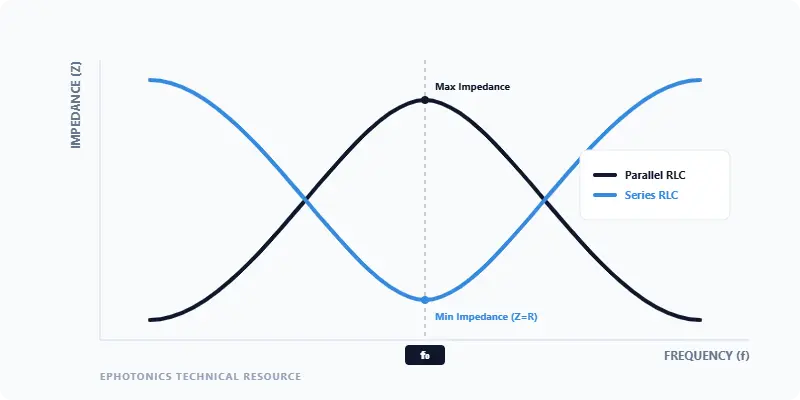
Figure 1: Resonance behavior in RLC circuits. In a Series configuration, impedance is at its minimum at \(f_0\), allowing maximum current. In a Parallel configuration, the circuit reaches maximum impedance, effectively "rejecting" the resonant frequency.
Quick Reference
- Resonance: Occurs when Inductive Reactance (\(X_L\)) equals Capacitive Reactance (\(X_C\)).
- Quality Factor (Q): A dimensionless parameter that describes how under-damped an oscillator is. Higher Q means a sharper resonance peak.
- Phase Angle: Represents the shift between voltage and current. At resonance, the phase angle is 0° (purely resistive).
- Bandwidth: The range of frequencies for which the power is at least half the peak power.
Typical RLC Operating Frequencies by Application
Logarithmic scale showing the vast range of RLC circuit utility
Hz
kHz
MHz
GHz
THz
Audio Filters
AM Radio Tuning
FM / VHF Radio
WiFi / Bluetooth
Optical Modulators
Source: Standard telecommunication and photonic system specifications.