Why use a Mode Field Diameter Calculator?
Why this matters- Coupling Efficiency: Mismatched MFDs cause significant signal loss (dB) at fiber junctions.
- Bend Loss Prediction: Larger MFDs are more susceptible to macro-bending losses.
- Splicing Accuracy: Minimizes splice loss by predicting mode overlap between dissimilar fibers.
- Beam Propagation: Determines beam divergence when light exits the fiber into free space.
Understanding the "Effective" Size of Light
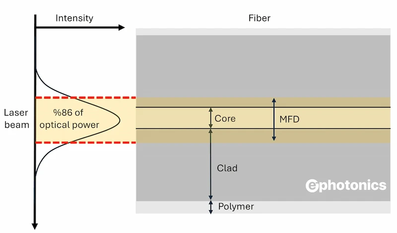
In single-mode fibers, light does not simply stay confined to the physical core. A significant portion of the optical power travels in the cladding as an evanescent field. The Mode Field Diameter (MFD) is the theoretical "spot size" that represents this intensity distribution, typically approximated as a Gaussian profile.
Unlike the core diameter (which is a fixed physical dimension, e.g., 9 µm for SMF-28), the MFD varies with wavelength. As wavelength increases, the mode spreads further into the cladding, increasing the MFD. Calculating this value is critical because it—not the core size—determines how well light couples into lenses, waveguides, or other fibers.
Critical Applications
1. Fiber-to-Fiber Splicing
When splicing two different fibers (e.g., SMF-28 to specialized fiber), splice loss is dominated by MFD mismatch, not core misalignment. This calculator helps predict that loss.
2. Free-Space Coupling
To focus a laser into a fiber with maximum efficiency, the focused spot size of your lens must match the fiber's MFD, not its core diameter.
3. High-Power Laser Safety
In high-power fiber lasers, a larger MFD reduces non-linear effects (like Stimulated Brillouin Scattering) by lowering the power density per unit area.
4. Micro-Bending Sensitivity
Fibers with smaller MFDs confine light more tightly, making them more resistant to bend losses—critical for compact photonic device packaging.
What affects Mode Field Diameter?
The MFD is governed by the V-Number (Normalized Frequency) of the fiber:
1. Wavelength: Longer wavelengths result in a larger MFD (weaker confinement).
2. Core Radius: A smaller core can actually increase MFD if it pushes the mode into the cladding (at low V-numbers).
3. Numerical Aperture (NA): A higher NA results in stronger confinement and a smaller MFD.
Deep Dive Article
Mode Field Diameter: The Real Size of Light
Learn the derivation of Marcuse's equation, how MFD impacts splice loss, and why it differs from core diameter.
→
Never miss a calculation.
Follow ephotonics on LinkedIn for daily updates.
Related Engineering Tools