Fiber Splice Loss Calculator
Fiber Optics · Splice Loss · Mode Field Diameter
ephotonics
linkedin.com/company/ephotonics
Follow us for weekly fusion splicing tutorials, fiber alignment tips, and new photonics tools.
Follow on LinkedInHow the Fiber Splice Loss Calculator Works
Splice loss occurs whenever the mode fields of two joined fibers do not perfectly overlap. In single-mode fibers, light travels as a Gaussian beam. This tool uses the Marcuse Gaussian Approximation to calculate losses from intrinsic mismatch and extrinsic alignment errors.
The Theory of Fiber Splice Losss
Understanding the Variables:
- w1, w2 Mode Field Radius: Half of the Mode Field Diameter (MFD/2).
- d Lateral Offset: The physical distance between the core centers of the two fibers.
- θ Angular Tilt: The angle between the two fiber axes (calculated in Radians).
- n Refractive Index: The core index of the fiber (typically ~1.46 for SMF-28).
- λ Wavelength: The operating wavelength of the system (nm).
The Physics of Fusion Splicing
Achieving a low-loss splice is the "Holy Grail" of fiber optics manufacturing. While modern fusion splicers use advanced machine vision to align fibers, the laws of physics impose strict limits on transmission efficiency.
Even if two fibers are perfectly aligned by the machine, signal loss can still occur due to physical differences between the glass waveguides. This calculator breaks down the loss into two categories: Intrinsic (Fiber Mismatch) and Extrinsic (Alignment Errors).
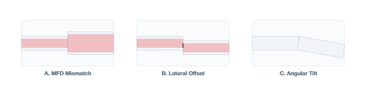
1. Intrinsic Loss (MFD Mismatch)
Intrinsic loss is caused by the manufacturing tolerances of the fiber itself. The most critical factor is the Mode Field Diameter (MFD).
This is governed by the Marcuse Gaussian approximation. The loss is symmetric regardless of direction (Large to Small vs. Small to Large) because of the "Reciprocity Principle" in optics.
2. Extrinsic Loss (Alignment)
Extrinsic loss is caused by the splicing process or the equipment quality. There are two primary mechanical errors:
A. Lateral Offset (d)
This occurs when the core centers do not align. Even a 0.5 µm error (invisible to the naked eye) can cause >0.1 dB loss. This is common in "V-Groove" splicers (Clad Alignment) where the machine aligns the outside of the glass, ignoring core eccentricity (concentricity error).
B. Angular Tilt (θ)
If the fiber cleave angle is not perfect (i.e., not exactly 90°), the fibers will meet at an angle. This forces the light path to "bend" sharply, radiating energy out of the core mode. Good cleavers should consistently produce angles < 0.5°.
Variable Definitions:
- w : Mode Field Radius (MFD / 2).
- d : Lateral offset distance.
- θ : Angular misalignment in Radians.
- n : Refractive index of the fiber core.
In standard telecom (mW power levels), a 0.5 dB splice loss just means a weaker signal.
In kilowatt-class fiber lasers, a 0.5 dB loss means ~10% of the power is dumped into the splice point. If you are running 1 kW, that is 100 Watts of heat generated instantly at the splice. This will cause the fiber to glow, melt, or explode.
For high-power applications, splice loss must be maintained below 0.02 dB using Active Core Alignment and careful thermal management.
Troubleshooting Splice Quality
If your calculated loss is low but your actual measured loss is high, check these common physical defects that this calculator cannot predict:
- Bubbles: Caused by dust or dirt on the fiber end-face before fusion.
- Necking (Waist): The splice current was too low or the push distance was insufficient, causing the fiber to thin out at the joint.
- Bulge (Fat Splice): Too much push distance or excessive arc power caused the glass to shove together too hard.
- Arc Duration: MFD can sometimes be expanded intentionally by "over-cooking" the splice (diffusion), creating a tapered transition (MFA) to match dissimilar fibers.